MicroPython’s WebREPL on the ESP8266

The NodeMCU ESP8266 device has built in WiFi. This allows us to, among other things, connect to the device through it’s own network to run commands. I walked through how connecting to a MicroPython enabled NodeMCU device is accomplished through the serial port in this post. I’d like to take a look now how to utilize another access feature that pairing MicroPython with an ESP8266 device allows, the WebREPL.

The WebREPL is a web based interface for the Read-Evaluate-Print-Loop (REPL) which allows for running commands on the ESP8266 in the same fashion as the terminal REPL does. However, since it is done through a wireless network connection it opens up some additional freedom for access. Of course having a device up and running on a network also poses some potential security issues, but we’ll look at those in another post.

Enable WebREPL

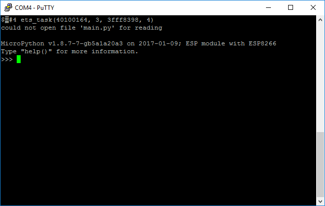
First thing first though, let’s assume that MicroPython is running on an ESP8266 device and you have a serial connection to the device. Again, have a look at my post here for that walk through. Assuming that you have flashed the ESP8266 with the latest version of MicroPython, version 1.8.7 as of this writing, the WebREPL must be enabled through the serial interface. It is a one line command to do from a command prompt:

import webrepl_setup

Entering in this command will produce a series of setup prompts, asking if you want WebREPL to be enabled at boot time, to set a password for the WebREPL, and to confirm rebooting the device to activate the changes.

Connect to Network

Once the system reboots you can connect to the device via WiFi. This is one of the neat features of these devices. If the board doesn’t connect to a wireless access point, it creates one for us. One can then connect to it via our computer or other wireless device. Look for an advertised WiFi network with a name of MicroPython-. The  will be a set of letters and numbers unique to each device.

Set Password

Upon selecting the device’s network you will need a password. The network password for the access point is micropythoN (note the capitalization of the last letter there). You should then be connected to the device’s network, congratulations!

Now in many situations one could simply browse to the device’s IP address in a browser and get some form of web page, such as our WebREPL interface. Remember that we are dealing with a device with limited memory here and, therefore, doesn’t have the actual webpage. Instead it provides a convenient websocket interface which can be used with the WebREPL Client. You can download it below:

Download MicroPython WebREPL Client

Once downloaded and unzipped you’ll want to open webrepl.html in either Chrome or Firefox (the browsers currently supported by WebREPL) You should see a screen similar to:

With your computer is connected to the device on the MicroPython network and using the default IP address and port of ws://192.168.4.1:8266 you can select the Connect button to start a WebREPL session.

You should see a prompt to enter your password, which is the one you set after enabling the WebREPL service on the device earlier. Once logged into the device you have access to the REPL just like you would from a serial connection.

Congratulations! You have just connected a NodeMCU ESP8266 to a wireless network with MicroPython. Not too horrible of a task, right?


Follow me on Twitter @kenwalger to get the latest updates on my postings on MicroPython and IoT.

Facebooktwitterredditlinkedinmail

MicroPython and the NodeMCU ESP8266

In a previous post, I looked briefly at MicroPython and it’s place and role in the Internet of Things (IoT) arena. In this post, I’d like to walk through the process of getting a NodeMCU ESP8266 device flashed and up and running with MicroPython. Then we’ll do the, almost required, IoT version of “Hello World”… a blinking LED light.

There are multiple micro-controller options available for using MicroPython so why, you may ask, have I decided on the NodeMCU? First and foremost they are inexpensive. You can find the NodeMCU ESP8266 development boards on eBay for under $5.00. Granted that is from a factory overseas, but for under $10.00 you can get one on Amazon. The second reason I like this board, in particular, is that it has LED lights built into the board so I don’t necessarily need to break out LED bulbs and resistors. Another big plus is that it is WiFi ready and with MicroPython that means that one can set up a web interface with the board and also readily make truly connected projects without additional hardware.

All that said and done I’ll be using a basic NodeMCU ESP8266 device for this tutorial. Feel free to use a different physical device with the same chip, just know that some settings may be different based on the physical device configuration. The board has a USB interface which, when connected to a PC provides power.

Firmware

We obviously need to get a copy of the MicroPython firmware. It comes in a .bin file format that can be loaded directly to the ESP8266 device and can be downloaded from the MicroPython site here. For this tutorial, I will be using the esp8266-20170108-v1.8.7.bin version of firmware. You will want to download that to your computer and remember where it is saved.

Now we need to deploy the firmware to our device. If you are using the above-mentioned board, deploying the firmware should be relatively straight forward. If you are using a different ESP8266 board, check with the manufacturer of your board for the proper flashing technique. For the rest of us, we will want to start with the esptool and use it to move the firmware over to our device. The tool can either be downloaded from GitHub directly or can be installed using pip with:

python -m pip install esptool

This version of esptool supports Python version 3.4 or newer.

Serial Ports

Once we have that installed on our system and the device connected via the USB port, we should, for best practice, clear the device by erasing its current state. Assuming that the port name of the device is COM4, we can accomplish that with the following command:

esptool.py --port COM4 erase_flash

Just substitute COM4 for whichever communication port your particular device is using. It may be something similar to /dev/ttyUSB1 on a non Windows machine and from a terminal port, you can use the command ls /dev/tty.* to detect the port. Also, depending on your ESP8266 device you might need to install the USB to UART Bridge VCP Drivers the be able to detect the device via a serial connection. Once the device has been flashed (it takes less than 10 seconds on my machine) we upload the firmware to the device with the following command:

esptool.py --port COM4 --baud 460800 write_flash --flash_size=detect 0 esp8266-20170108-v1.8.7.bin

The filename of the firmware should match the downloaded firmware. Assuming you don’t get any errors during the flashing process, you now have a NodeMCU ESP8266 device running MicroPython. Pretty slick, eh?

Serial Terminal

We can now connect to the device using a serial terminal tool, like PuTTY for Windows, the screen program on Mac, or something like picocom for Linux. I’ll be using PuTTY since I’m currently on a Windows 10 machine.

We’ll want to select our serial port again, in my case it is COM4 and set the speed, or baud rate, to 115200. Then we can open the connection and we should be prompted with a Python read-evaluate-print-loop (REPL) interface as shown:

We can start entering in Python commands on the device itself. Let’s have our device do the IoT version of “Hello World” and turn on one of the on-board LED lights. These lights are controlled through General-Purpose Input/Output (GPIO) pins and there are two of them on board. GPIO 2 controls a small blue LED on the board.

In the REPL then, we want to be able to turn the light on and off. That can be done by altering the state (electrical charge) provided to the GPIO pins, typically by changing the state from low to high and back to low.

Here is something that I discovered when working with this particular LED and GPIO setting and board. On this board, the LED on GPIO 2 (and 16 for that matter) is wired between the pin and the power, so when we set the pin state to low, the light is activated, and when set to high, it is off. There is active development on this issue and firmware updates may have already addressed the issue. However, if one connects an external LED light to, say GPIO 5 along with the required resistor (~300+ ohms), we get the expected light on with a high state, and off with a low state.

MicroPython code – Try it Out!

Okay, so technical issues aside, let’s look at the code necessary to turn on our LED. First, we’ll need access to the board’s hardware. We can import a package called machine which provides the necessary software interface. Then we can change the state of a given GPIO pin…

>>> import machine
>>> pin = machine.Pin(2, machine.Pin.OUT)
>>> pin.high()  # light off
>>> pin.low()  # light on
>>> pin.high() # light off again

There we have it! We have taken a NodeMCU 8266 device, flashed it with MicroPython, accessed it through the serial port, and with minimal code, turned the on-board LED lights on and off.

Congratulations on your first venture into IoT and Python! There is a lot more that can be done with this $5.00 board and I think I will spend some time experimenting with it a bit. I’ll post my results and findings here as I work through the process.


Follow me on Twitter @kenwalger to get the latest updates on my postings.

Facebooktwitterredditlinkedinmail