Another round of tech layoffs rolled through the industry recently, and I was one of the people caught in it.
If you’ve worked in tech for any length of time, you know the routine that follows. Update the résumé. Reach out to contacts. Scroll job boards. Try to figure out which technologies the market is currently excited about and which ones have quietly drifted into irrelevance.
After a few days of that cycle, I found myself spending more time outside than in front of a laptop.
One afternoon, walking around the yard, I noticed something interesting.
My backyard contains a surprisingly large dataset.
Rocks.
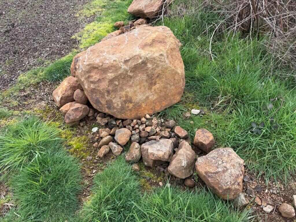
Lots of rocks.
Some are the size of peas. Others are roughly the size of a car engine. A few fall somewhere in the unsettling range between “wheelbarrow recommended” and “this probably requires heavy machinery.”
Naturally, I had the same thought many people eventually have when staring at a large pile of rocks:
I could probably sell these.
A small stand near the road. A few piles sorted by size. Maybe a sign that says “Landscaping Rock.” It’s not exactly a venture-backed startup, but stranger side businesses have existed.
Unfortunately, engineers have a well-known weakness.
We rarely do things the simple way.
If I was going to sell rocks, I wasn’t just going to pile them on a table.
I was going to build a system.
The Dataset
The moment you start thinking about the rocks as inventory, a familiar set of questions appears.
How many rocks are there?
What kinds?
Which ones are small decorative stones and which ones fall firmly into what I’ve started calling Engine Block Class?
Like many real-world datasets, this one has significant variability.
Some objects are a few grams. Others weigh enough to require careful lifting technique and a brief internal conversation about life choices.
At a glance, the dataset looks chaotic. But underneath the chaos are patterns.
Different sizes. Different shapes. Different colors. Different geological types. Some rocks are smooth river stones. Others are jagged fragments that look like they escaped from a small landslide.
If you squint a little, you start to see the outlines of something familiar to anyone who works with data systems.
A collection of physical objects that could be represented as structured records.
The Engineer’s Curse
In theory, selling rocks is simple.
- Step one: collect rocks.
- Step two: put them in a pile.
- Step three: wait for someone to stop their car and decide they want landscaping material.
But once you start thinking about it from an engineering perspective, the questions multiply.
Should each rock have an identifier?
Should there be photographs?
Should the system track weight or dimensions?
What about classification?
It’s probably useful to distinguish between Pebble Class rocks and Wheelbarrow Class rocks.
And what about the really large ones — the ones that are clearly in the Engine Block Class, which itself appears to span everything from motorcycle engine scale to something closer to a semi-truck.
Once you start thinking about these questions, the simple rock pile begins to look like something else entirely.
A catalog.
A dataset.
A system waiting to happen.
From Rocks to Records
What if every rock had a record?
Something simple at first.
An identifier. A few attributes. Maybe a photo.
Conceptually, it might look like this:
rock_id
weight
dimensions
color
rock_type
location_found
status
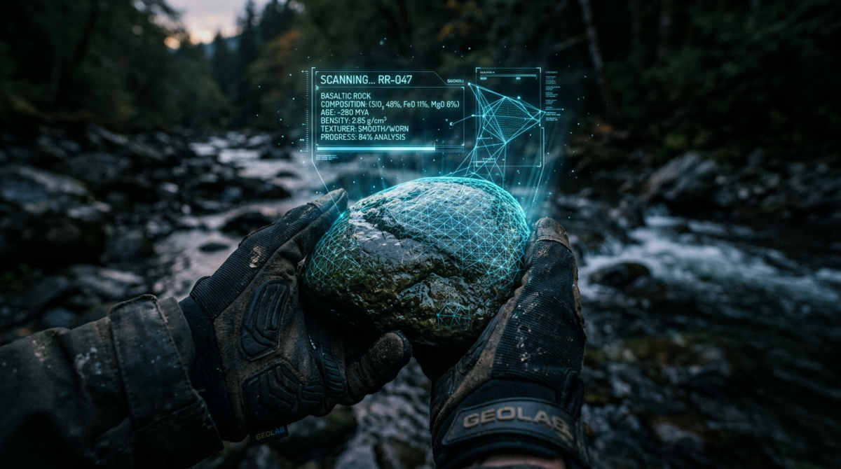
Each rock in the yard becomes a digital object — a structured record representing something in the physical world.
In other words, each rock now has a digital twin.
That might sound slightly ridiculous in the context of landscaping stones, but the idea is surprisingly powerful.
Across many industries, organizations are trying to solve exactly this problem: how to connect messy physical reality with structured digital systems.
Manufacturers track machine parts.
Museums catalog artifacts.
Farmers track crops.
Logistics companies track inventory moving through warehouses.
In each case, the challenge is similar.
A physical object exists somewhere in the world.
We want to represent it in a way that software systems can understand.
The Backyard Quarry
At this point the rock pile had acquired a new name.
The Backyard Quarry.
Partly as a joke, and partly because it captured the spirit of the project. What started as a casual observation had turned into a small experiment in data modeling, object cataloging, and system design.
The dataset might be small.
The objects might be rocks.
But the underlying questions are surprisingly rich.
How do you represent physical objects in software?
How do you capture information about them?
How do you search and organize the resulting data?
And how do these systems scale when the number of objects grows from a few dozen to thousands — or millions?
What Comes Next
Over the next few posts in this series, I’m going to explore those questions by building a small system around the Backyard Quarry.
We’ll look at things like:
- designing a schema for physical objects
- capturing images and measurements
- generating 3D models using photogrammetry
- building ingestion pipelines
- indexing and searching the dataset
All starting from a simple collection of rocks.
The world has no shortage of complicated engineering problems.
Sometimes the best place to explore them is somewhere simpler.
Like a pile of rocks in the backyard.
And if you happen to need a carefully documented specimen from the Backyard Quarry, inventory is currently available.
Shipping, however, may exceed the value of the rock itself.
The Rock Quarry Series
- Turning Rocks into Data – This Post
- Designing a Schema for Physical Objects
- Capturing the Physical World
- Searching a Pile of Rocks
- Digital Twins for Physical Objects
- Scaling the Quarry
- Systems Beyond the Backyard
- From Rocks to Reality